

 English
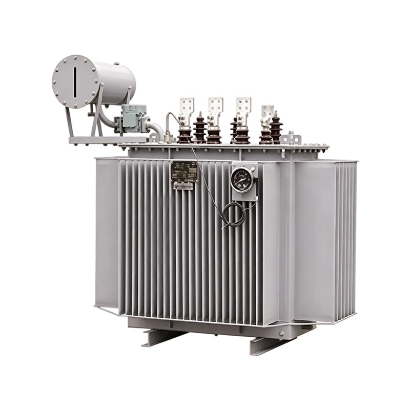
S11/S13/S20/S22 10kV oil-immersed distribution transformers (50-4000kVA) are widely used in 10kV distribution networks for direct power supply to end users. Typical applications include rural township...
View More
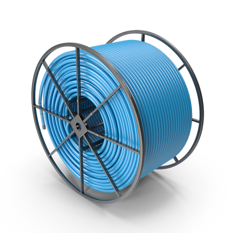
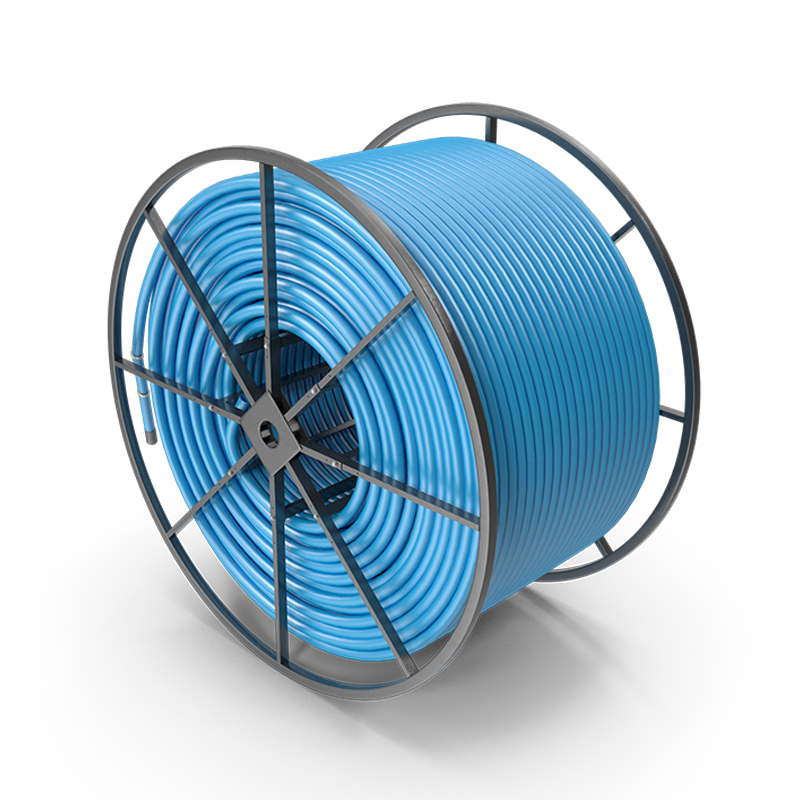
IEC Standard XLPE Insulated Medium Voltage Power Cable
Product OverviewXLPE insulated medium voltage power cables are thermosetting insulated power cables manufactured using a chemical cross-linking process that transforms the polyethylene molecular structure from linear to a three-dimensional network. This product is widely used in power transmission and distribution systems at voltage grades of 35 kV and below, serving as a carrier for electrical energy transmission. XLPE cables not only possess sound electrical properties, mechanical strength, heat and ageing resistance, environmental stress resistance, and chemical corrosion resistance, but also feature a simple construction, light weight, and unrestricted installation elevation differences, making them a forward-looking product in power cable development.
- Product Advantages
- Product Specifications
-
Standards Basis
This series is designed, manufactured, and tested in strict accordance with the following IEC international standards and relevant national standards:IEC 60502-2:2014 – Power cables with extruded insulation and their accessories for rated voltages from 1 kV up to 30 kApplicable to fixed-installation extruded insulation power cable systems for rated voltages from 6 kV up to 30 kV, specifying cable design, construction, dimensions, and test methods.
IEC 60840:2020 – Power cables with extruded insulation and their accessories for rated voltages above 30 kV up to 150 kApplicable to test methods and requirements for high voltage XLPE insulated power cables.
GB/T 12706.2-2020 – Extruded insulation power cables and accessories for rated voltages from 6 kV up to 30 kNational standard equivalent to IEC 60502-2.
GB/T 12706.3-2020 – Extruded insulation power cables and accessories for rated voltage of 35 kNational standard equivalent to IEC 60502-2.
GB/T 19666-2019 – General rules for flame retardant and fire-resistant wires and cables. Requirements for flame retardant and fire-resistant performance.Core note: The IEC 60502-2:2014 standard is specifically applicable to extruded insulation power cables for rated voltages from 6 kV (Um = 7.2 kV) up to 30 kV (Um = 36 kV), covering various insulation materials including cross-linked polyethylene (XLPE), polyvinyl chloride (PVC), and ethylene propylene rubber (EPR). This standard sets out complete technical requirements for cable design, construction, dimensions, and test methods to ensure the safety and reliability of cables in power transmission and distribution.
Product Structure
The basic structure of XLPE insulated medium voltage power cables is as follows (taking the armoured type as an example):Triple-Layer Co-Extruded Core Structure
Conductor: Uses Class 2 stranded copper conductor or aluminium conductor, circular compacted construction, complying with IEC 60228 / GB/T 3956 requirements. Large cross-section conductors use a segmented conductor construction, with roundness diameter deviation controlled within ±0.5% D, effectively reducing skin effect and proximity effect to increase transmission capacity.
Conductor screen: A layer of semi-conductive cross-linked compound is extruded over the conductor surface, completely covering it. This serves to uniform the electric field and prevent partial discharge between the conductor and insulation layer.
Insulation layer: The main insulation material is cross-linked polyethylene (XLPE), using a fully dry chemical cross-linking process that transforms thermoplastic polyethylene into thermosetting cross-linked polyethylene. Mechanical properties and thermal ageing resistance are significantly improved. The insulation layer is uniform and dense, with high dielectric strength.
Insulation screen: A layer of semi-conductive cross-linked compound is extruded over the insulation layer, bonding tightly with it to further uniform the electric field distribution.Metallic Screen and Armour Layer
Metallic screen: Uses copper tape lapping or copper wire braiding/concentric stranding construction. It carries fault current during a cable short circuit and provides electromagnetic shielding under normal operating conditions.
Inner sheath/separator: Appropriate separator material is provided based on the armour type.
Armour layer: Depending on the usage environment and mechanical protection requirements, the following armour forms can be selected:
- Double steel tape armour (code "2"): Suitable for applications subject to certain mechanical external forces but not excessive tensile force.
- Fine round steel wire armour (code "3"): Suitable for high elevation difference areas, capable of withstanding mechanical external forces and considerable tensile force.
Outer sheath: Uses polyvinyl chloride (PVC), polyethylene (PE), or low-smoke zero-halogen (LSZH) material, providing mechanical protection, environmental protection, and anti-corrosion protection. Special properties such as UV resistance, oil resistance, anti-termite, and anti-rodent can be optionally provided.Technical Parameters
Rated Voltage Grades
U₀/U (kV): 3.6/6, 6/6, 6/10, 8.7/10, 8.7/15, 12/20, 18/20, 18/30, 21/35, 26/35.
U₀ is the voltage between conductor and earth, U is the voltage between conductors.
Note: The maximum operating voltage of the cable is 1.2 to 1.5 times the rated voltage.Nominal Cross-Sectional Area Range
Single-core armoured (1 core): 25–800 mm², maximum up to 1200 mm².
Multi-core armoured (3 cores): 25–500 mm².Operating Temperature Parameters
Maximum continuous normal operating temperature: 90 °C (per IEC 60502-2).
Maximum short-circuit temperature (≤ 5 seconds): 250 °C (per IEC 60502-2).
Minimum installation temperature: Not lower than 0 °C (preheating required if below this) (per IEC 60502-2).Minimum Bending Radius (During Installation)
Single-core cable, armoured: ≥ 15 × cable outer diameter (D); non-armoured: ≥ 20 × D.
Multi-core cable, armoured: ≥ 12 × cable outer diameter (D); non-armoured: ≥ 15 × D.Flame Retardant Standards
The product complies with the following flame retardant standard requirements:
- IEC 60332-1: Vertical flame test for a single cable.
- IEC 60332-3: Vertical flame test for bunched cables (Class A/B/C flame retardant; Class C is the basic requirement).
- LSZH: Low-smoke zero-halogen flame retardant standard (optional).
Special performance requirements such as Class A, B, C flame retardant, fire-resistant, anti-termite, and anti-rodent can also be met.Conductor DC Resistance (Typical Values)
Nominal Cross-Section 50 mm²: Copper conductor max. 0.387 Ω/km, Aluminium conductor max. 0.641 Ω/km.
Nominal Cross-Section 70 mm²: Copper conductor max. 0.268 Ω/km, Aluminium conductor max. 0.443 Ω/km.
Nominal Cross-Section 95 mm²: Copper conductor max. 0.193 Ω/km, Aluminium conductor max. 0.320 Ω/km.
Nominal Cross-Section 120 mm²: Copper conductor max. 0.153 Ω/km, Aluminium conductor max. 0.253 Ω/km.
Nominal Cross-Section 150 mm²: Copper conductor max. 0.124 Ω/km, Aluminium conductor max. 0.206 Ω/km.
Nominal Cross-Section 185 mm²: Copper conductor max. 0.0991 Ω/km, Aluminium conductor max. 0.164 Ω/km.
Nominal Cross-Section 240 mm²: Copper conductor max. 0.0754 Ω/km, Aluminium conductor max. 0.125 Ω/km.
Nominal Cross-Section 300 mm²: Copper conductor max. 0.0601 Ω/km, Aluminium conductor max. 0.100 Ω/km.
Nominal Cross-Section 400 mm²: Copper conductor max. 0.0470 Ω/km, Aluminium conductor max. 0.0778 Ω/km.
Nominal Cross-Section 500 mm²: Copper conductor max. 0.0366 Ω/km, Aluminium conductor max. 0.0605 Ω/km.
Nominal Cross-Section 630 mm²: Copper conductor max. 0.0283 Ω/km, Aluminium conductor max. 0.0469 Ω/km.
Data source: GB/T 3956 / IEC 60228 standard.Model Designation System
The model designation of XLPE insulated medium voltage power cables follows a unified rule. The meaning of each component is as follows:
Conductor material: Omitted for copper conductor; L for aluminium conductor.
Insulation material: YJ for cross-linked polyethylene (XLPE) insulation.
Metallic screen: Omitted for copper tape screen; S for copper wire screen.
Armour type: 2 for double steel tape armour; 3 for fine round steel wire armour; 4 for coarse round steel wire armour; 6 for non-magnetic metal tape armour; 7 for non-magnetic metal wire armour.
Outer sheath: 2 for polyvinyl chloride (PVC) outer sheath; 3 for polyethylene (PE) or polyolefin outer sheath.
Characteristic codes: Z/ZA/ZB/ZC for flame retardant (Class A/B/C); WDZ/WDZA/WDZB/WDZC for halogen-free low-smoke flame retardant; N for fire-resistant.Common Model Examples
YJV / YJLV: XLPE insulated PVC sheathed power cable. For indoor, tunnels, cable trenches, and ducts; can withstand certain pulling force but not mechanical external forces.
YJV22 / YJLV22: XLPE insulated steel tape armoured PVC sheathed power cable. For indoor, tunnels, cable trenches, direct burial; can withstand mechanical external forces but not large tensile forces.
YJV32 / YJLV32: XLPE insulated fine round steel wire armoured PVC sheathed power cable. For high elevation difference areas; can withstand mechanical external forces and considerable tensile force.
YJV62: XLPE insulated double non-magnetic metal tape armoured PVC sheathed power cable. For AC circuit single-core cables, using non-magnetic material armour.
ZC-YJY23: Flame retardant Class C XLPE insulated steel tape armoured polyethylene sheathed power cable. For direct burial underground, cable trenches, tunnels, and other fixed installations requiring mechanical protection.
Model designation system based on GB/T 12706 and GB/T 19666 standards.Electrical Performance
Partial Discharge
According to IEC 60502-2, the finished cable shall undergo a partial discharge test. The partial discharge magnitude at the specified test voltage shall meet the standard limit requirements, ensuring the cable operates stably over the long term at operating voltage.Power-Frequency Voltage Withstand Test
The finished cable shall withstand a power-frequency AC voltage withstand test at the specified voltage for the specified duration. No breakdown of the insulation is acceptable.
According to standard: IEC 60502-2:2014 provides complete technical specifications for cable test methods.Application Scope
IEC standard XLPE insulated medium voltage power cables are widely used in the following fields:
- Urban power grids: Serving as backbone mains for urban transmission and distribution networks, undertaking power distribution and transmission tasks.
- Industrial distribution systems: Internal distribution systems of various factories and industrial parks.
- New energy sector: Power transmission under extreme conditions for solar power plants, wind turbines, and energy storage facilities.
- High-rise buildings: Distribution mains and fire protection equipment power supply for high-rise buildings.
- Municipal engineering: Fixed installation environments such as direct burial underground, cable trenches, tunnels, bridges, and ducts.
- Special applications: Flame retardant, fire-resistant, or halogen-free low-smoke type cables can be selected for locations with high fire protection requirements; marine cables meeting IEC 60092-354 requirements can be used for various ships and offshore structures such as offshore oil platforms.Selection Guide
Installation Method and Model Selection
- Overhead/indoor/cable tray: YJV/YJY, unarmoured type, can withstand certain pulling force.
- Direct burial/cable trench: YJV22/YJY23, steel tape armoured, withstands mechanical external forces.
- High elevation difference/shaft: YJV32/YJY33, steel wire armoured, withstands considerable tensile force.
- AC circuit single-core: YJV62/YJV63, non-magnetic metal armoured, avoids eddy current losses.
- High fire protection requirements: ZA-YJV/WDZA-YJY, flame retardant/halogen-free low-smoke flame retardant type.Temperature Considerations
- Ambient temperature: The ambient temperature during cable installation should not be lower than 0 °C. If it is below 0 °C, heating measures must be taken before installation can proceed.
- Operating temperature: During normal long-term operation, the maximum conductor temperature can reach 90 °C, offering a higher current-carrying capacity and transmission capacity advantage compared with PVC insulated cables (70 °C).
- Short-circuit conditions: In the event of a short-circuit fault (duration ≤ 5 seconds), the maximum conductor temperature can reach 250 °C, providing a sufficient margin for safe operation under system emergency conditions. -
Model Voltage level Specification (number of cores x cross-sectional area) Execution standard Manufacturing branch CU(AL)/XLPE/CTS/PVC
CU(AL)/XLPE/CTS/PE
CU(AL)/XLPE/CTS/PVC/DSTA/PVC
CU(AL)/XLPE/CTS/PE/DSTA/PE
CU(AL)/XLPE/CTS/PVC/AWA/PVC
CU(AL)/XLPE/CTS/PE/AWA/PE
CU(AL)/XLPE/CTS/PVC/SWA/PVC
CU(AL)/XLPE/CTS/PE/SWA/PE
CU(AL)/XLPE/CWS/PVC
CU(AL)/XLPE/CWS/PE
CU(AL)/XLPE/CWS/PVC/DSTA/PVC
CU(AL)/XLPE/CWS/PE/DSTA/PE
CU(AL)/XLPE/CWS/PVC/AWA/PVC
CU(AL)/XLPE/CWS/PE/AWA/PE
CU(AL)/XLPE/CWS/PVC/SWA/PVC
CU(AL)/XLPE/CWS/PE/SWA/PE3.6/6kV 1×25~1×1000
3×25~3×500
IEC 60502-2-2024Medium Voltage Plant (South Plant, West Plant) 6/10kV 1×25~1×1000
3×25~3×500Medium Voltage Plant (South Plant, West Plant) 8.7/15kV 1×25~1×1000
3×25~3×500Medium Voltage Plant (South Plant, West Plant) 12/20kV 1×35~1×1000
3×35~3×500Medium Voltage Plant (South Plant, West Plant) 18/30kV 1×50~1×1000
3×50~3×500Medium Voltage Plant (South Plant, West Plant)
ABOUT US
Hixon (Changzhou) Science and Technology Innovation Investment Co., Ltd. is located in Changzhou, Jiangsu, China. It is a comprehensive trading company specializing in the export of industrial products. With years of international trade experience, the company has established strong channel resources and project collaboration experience in the African market.
By integrating high-quality manufacturing resources with a well-established supply chain, we provide reliable product supply and professional trade services to global customers, aiming to become an important bridge connecting Chinese manufacturing to the global market.
-
0Export Experience
-
0+Export Countries
-
0+Partner Factories
-
0+Global Customers
Related products
-
-
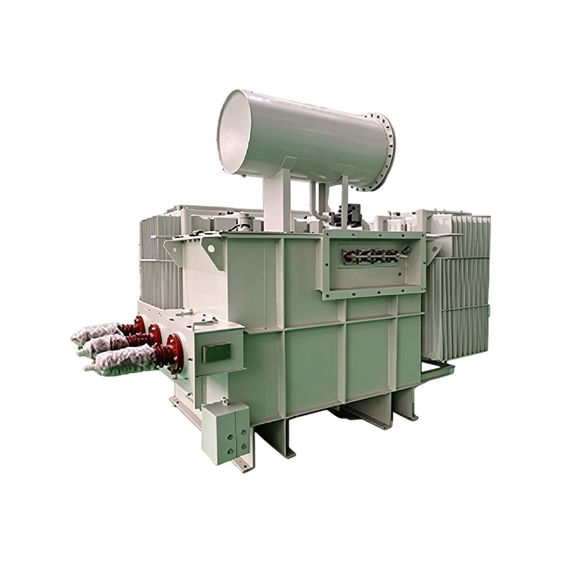
S11/S13/S18/S20/S22 35kV oil-immersed power transformers (50-63,000kVA) are primarily used in national grid infrastructure, renewable energy generation, petrochemical, metallurgical, mining, and trans...
View More -
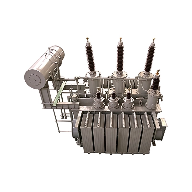
S11/S18/S20 110kV oil-immersed power transformers (6,300-180,000kVA) are core equipment in 110kV transmission and distribution systems, widely deployed in national grid projects, industrial and mining...
View More -
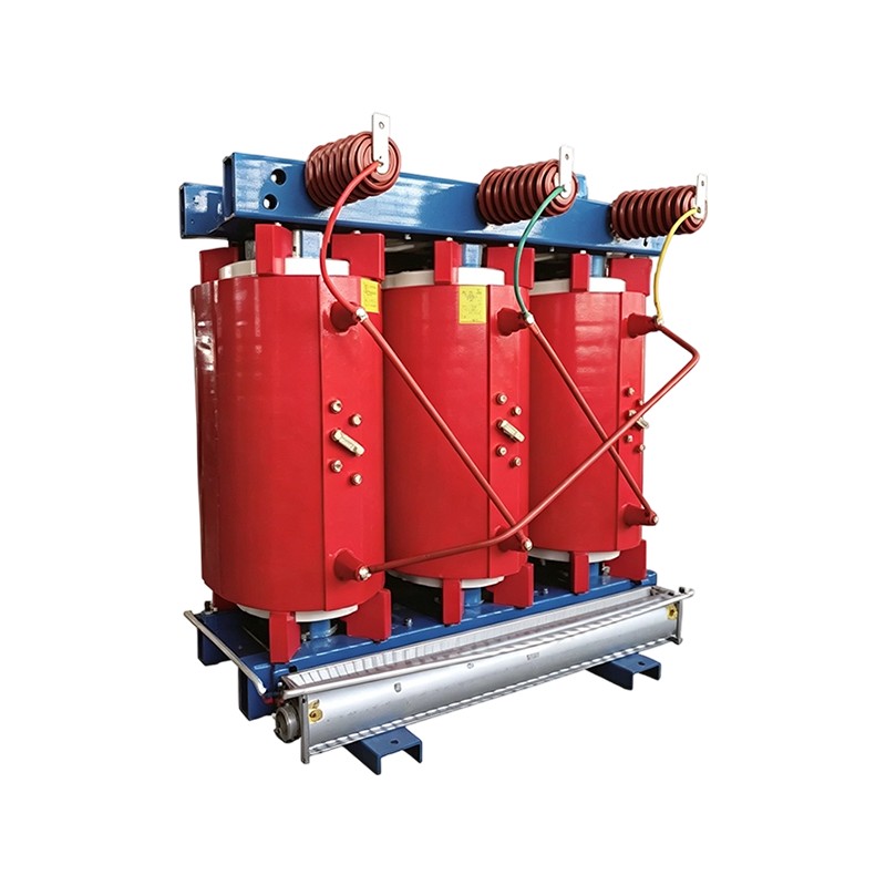
The SCB10/12/14/18 series energy-efficient dry-type cast resin transformer is a new-generation product developed on the basis of the SCB11, designed for reduced energy consumption, material savings, a...
View More -
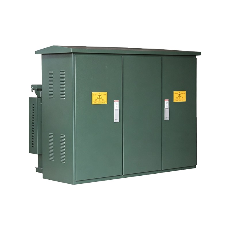
Product Overview:The ZGS series American-style pad-mounted transformer is developed by adapting the American-style combined substation concept to domestic application requirements. It features a compa...
View More -
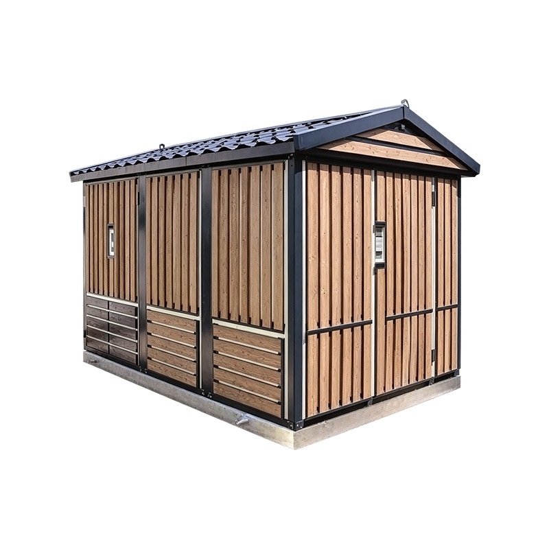
Product Overview:The YBW intelligent European-style prefabricated substation integrates high-voltage switchgear, instrument transformers, the power transformer, low-voltage switchgear, reactive power ...
View More -
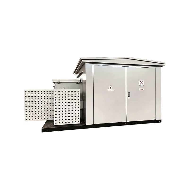
Product Overview:The YB series prefabricated step-up substation is developed to meet the power requirements of wind power generation and photovoltaic power generation, serving primarily as the first-s...
View More -
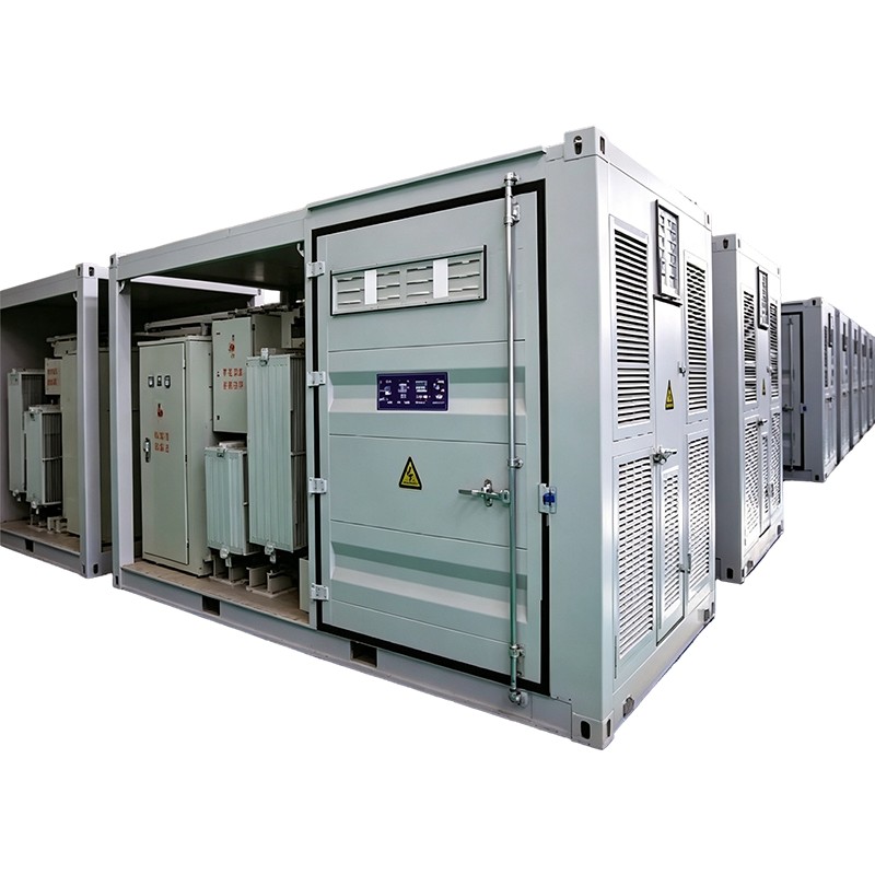
Product Overview:The YBW series prefabricated substation is developed to serve the operational requirements of wind power generation, photovoltaic power generation, shale gas extraction, and energy st...
View More -
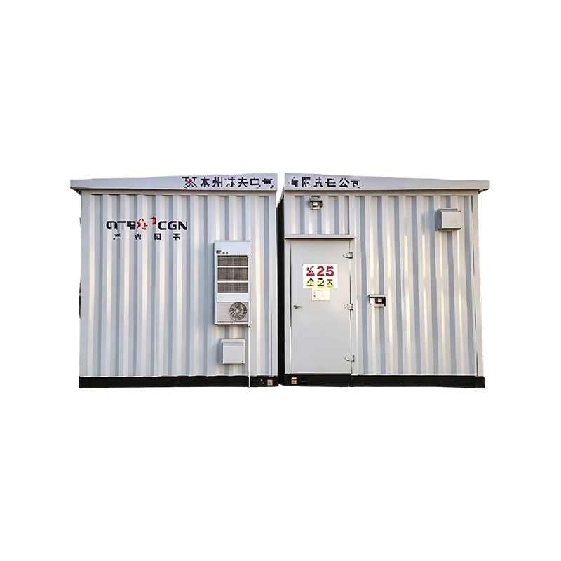
Product Overview:The YBW series centralized prefabricated container substation is developed to serve the operational requirements of wind power generation, photovoltaic power generation, and energy st...
View More -
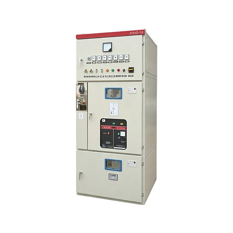
Product Overview:The XGN2-12 box-type fixed metal-enclosed switchgear is used in 3.6-12kV three-phase AC 50Hz indoor systems for power reception and distribution, and is particularly suited to frequen...
View More -
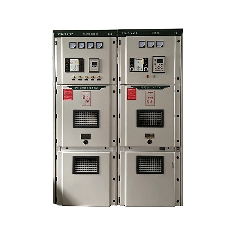
KYN28-12 Product Overview:The KYN28-12 armored withdrawable AC metal-enclosed switchgear is a three-phase AC 50Hz indoor switchgear assembly for receiving and distributing 3.6-12kV network power, with...
View More -
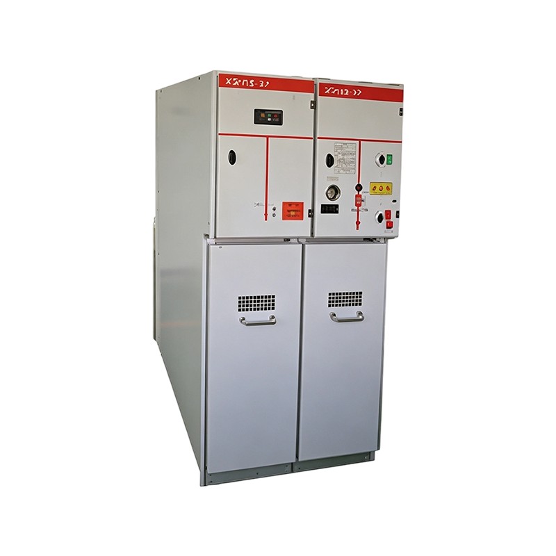
The XGN15-12 high voltage ring main unit (RMU) is a three-phase AC indoor box-type metal-enclosed switchgear with a rated voltage of 10kV and rated frequency of 50Hz. It is suitable for power distribu...
View More
NEWS & MEDIA
View More
-
 2026.05.14
 Company News
-
2026.05.14
Company News
-
2026.05.14
Company News
-
2026.05.14
Company News
-
2026.05.14
Company News

-
No. 108-2, Zhongguancun Avenue, Kunlun Sub-district, Liyang City, Changzhou City, China

-
+86 -13961488818

-
+86-0519-88328818

-
wendy@czhixon.com

jemy@czhixon.com
- About Us
- Company Overview
- Factory
- FAQ
- News
- Quick Links
- Home
- Lube Oil / Tyre
- Cable / Transformer
- About
- Service
- Contact
- QR Code
- Don't hesitate to contact when you need us!
© Copyright
Hixon (Changzhou) Science and Technology Innovation Investment Co., Ltd.
All Rights Reserved.

